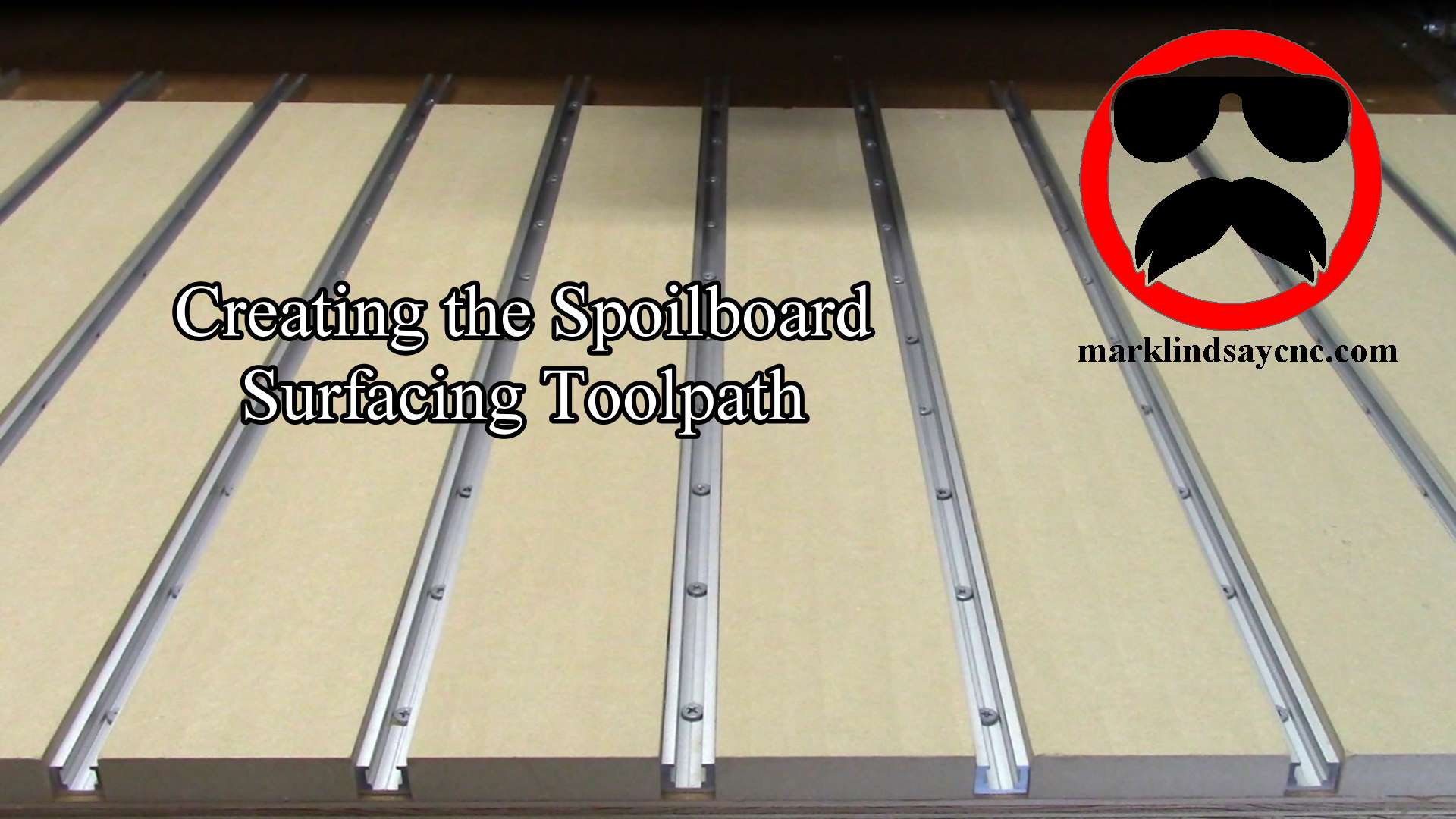
Creating a Spoilboard Surfacing Toolpath in VCarve
Surfacing a spoilboard is the final necessary step, after laying one down on the CNC table. Creating the surfacing toolpath sounds intimidating, but it’s actually pretty simple. You just have to remember a couple of things. [expand title=”Read More”]
Why Surface a Spoilboard?
The simple answer is that we surface the spoilboard to make sure that it’s flat and smooth. Material to be cut on the CNC is mounted to the spoilboard. We want that material to be as flat as possible to ensure smooth cuts of equal depth along every part of its surface.
This is especially important when it comes to v-carving or engraving. If the work piece isn’t sitting flat, a v-bit will cut deeper in areas that are sitting on a high spot, and shallower in areas that are sitting in a low spot.
Assuming you have trammed your router or spindle, and have your spoilboard mounted, we can start gathering the info we need to create a toolpath we can use to surface the spoilboard. If you haven’t trammed your router or spindle, I highly recommend you do so before you attempt to surface a spoilboard. I covered the process in my website article “Tramming the Router on my Gatton CNC,” which you can read here.
Things to Note and Remember
There are a couple of things we need to know before we get on the computer. Chief among them is the physical size of your spoilboard, and its proximity to your limits. We need to be sure that the toolpath we create will allow you to run the surfacing bit over the entire spoilboard without hitting a limit switch or crashing an axis.
When I made my spoilboard, I used a felt pen chucked into my router to draw a line on the table, from one side of my X axis to the other. I purposely triggered the limit switches at both ends of the X axis when I drew that line. I did that for several reasons, but one reason was to learn exactly where those limits were in relation to the centerline of the router bit over the table. It turns out that limit was roughly 1/4” away from the aluminum angle along each side of the table.
I put a piece of t-track right next to that aluminum angle, and it’s just shy of 3/4” wide. My spoilboard actually starts right next to that t-track. That means the left and right edges of my spoilboard are roughly 1/2” inboard of the limits of my X axis. This means I can safely machine the surface of the spoilboard without triggering a limit switch in X.
Along the Y axis, my CNC will run past the front edge of the table by a couple of inches without hitting the forward limit switch. I used that line I drew on the table to aid in placement of the spoilboard pieces, and trimmed the back edge of the spoilboard flush, using a 1/4” straight bit in my router. I know that the router will miss the rear Y axis limit switch by at least 3/8” – probably more.
With the measurements of the spoilboard in X and Y and the distance from each edge of the spoil board to each limit written down, I can get into VCarve Pro and start creating the toolpath.
Creating the Toolpath
Follow along in the video below as I go through the steps needed to create a toolpath for surfacing the spoilboard. I’m using VCarve Pro version 8.5, so some of the screens may differ from yours slightly, depending on which version you’re using.
We’ll be using some of the calculators built into the VCarve software to create the toolpath boundary. Then we’ll calculate a pocket toolpath, preview it, and make any adjustments needed. Finally, we’ll save the g-code.
As usual, if you have a question or comment, leave it in the comments section below. Or, if you’d prefer, go over to the Contact Us page and submit it to me there.
Until next time, take care and have fun! [/expand]
[amazon_link asins=‘B01H54ULSO,B000A804DA,B000ALY4E2,B000CD1T0A,B0000DCBK0,B00005QEVQ,B000C02BXW,B0002YQ3KA,B0000225XE,B019G0VVTI’ template=’ProductCarousel’ store=’malicn-20′ marketplace=’US’ link_id=’a61cfcca-ccd4-11e7-98ea-53defb9beaf6′]


7 Comments
DavidDeS
I want to say thank you. I got my spoilboard surfaced nice and smooth after following your instructions. It worked very well.
WadeTag
Thank You! Good Work!
MorieAbotte
Not as hard as I thought it would be. Thanks!
RobertD
Thank you.
Duff
Just what I was looking for
Tim
Nice tutorial! Very clear and concise, no steps were overlooked and good background info given as to why certain choices were being made. This helped me very much. Thank you, please make more videos!
Mark Lindsay
Thank you very much! I have more coming…