The CNC Process for the Absolute Beginner
For those who are absolute beginners at CNC, the questions you’ll have are undoubtedly numerous. Probably the best place to start is with a basic understanding of what a CNC router is and how the CNC process works.
CNC has become the generic term used to describe several different types of devices that are controlled by a computer; everything from a CNC router to a CNC lathe, CNC mill, CNC plasma cutter, etc. are all known as just a CNC by their enthusiasts. In this instance, I’m going to focus on a CNC router, as that’s what I’m most familiar with.
What is CNC?
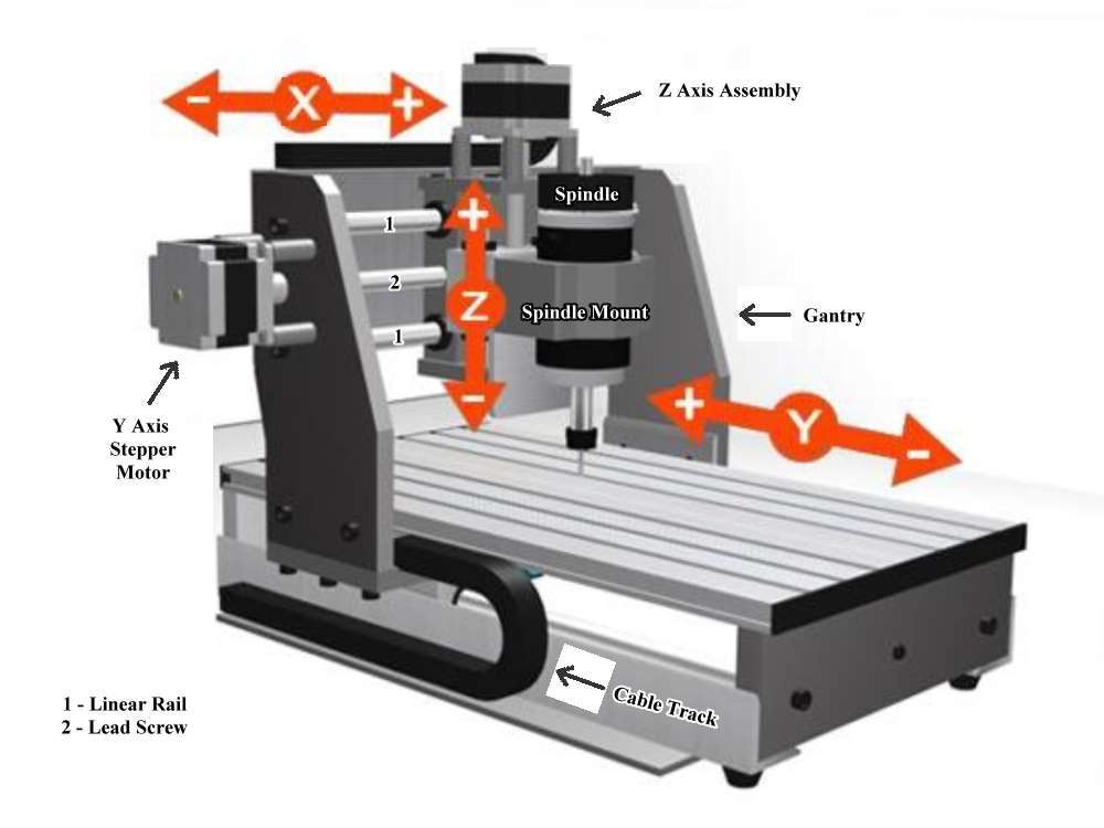
CNC stands for Computer Numerical Control. That means that the physical movements of the machine are controlled by a computer, via a complex mathematical coordinate system. A computer moves the router or spindle on the CNC in 3 directions or axes. The X axis (which always moves from side to side as you face the machine,) the Y axis (which always moves from front to rear as you face the machine,) and the Z axis (which always moves up and down.) These axes are labeled in the picture below.
CNC technology has been around since the 1940s, when a CNC mill was first controlled by an analog computer via a perforated tape or a series of punch cards. That system gradually gave way to an all-electronic control via a computerized code, which eventually led to the digital control we use today. The process used today in most home hobby CNC routers is the same basic system used by high end manufacturing facilities on machines costing millions of dollars. Their software is a lot more complex to be able to perform in such a high demand environment, and can cost several hundred thousand dollars, but the basic process is very similar.
What is a CNC Router?
The major parts of the CNC router can be broken down into several components. Those components include the Gantry Assembly, which moves along the Bed or Table of the router. The Gantry holds the Z Axis Assembly, which includes the router or spindle and its mount. A series of 3 or 4 Stepper Motors control the movement of the axes along a Linear Rail via the use of Lead Screws, Drive Belts or Chains, or a Rack and Pinion system of gears. The example below uses a lead screw drive system, in which a precision ground ACME threaded rod is threaded through a Lead Nut in the axis, then attached to the Stepper motor by a Coupler. When the stepper motor turns, it rotates the lead screw, causing the lead nut (and any assembly attached to it) to move back and forth along the length of the lead screw. The linear rails guide the axis assembly smoothly along the entire length of its travel. In the picture below, some of those components are labeled. All three of the CNC’s axes have a liner rail system, a lead screw, lead nut, and a stepper motor. Also not seen is a PC which has the controller software loaded on it. More on that soon.

Please understand from the beginning that a CNC router is NOT a miracle machine. It is just another tool to be added to the arsenal of tools already in your shop. The machine that can take material into one end and drop finished projects out the other end does not exist. No matter what tool you use, there will always be hand sanding, assembly, and finishing involved in the project’s completion. A CNC router is no different.
Additionally, a CNC is not always the best, fastest, or even most appropriate tool for a job. A CNC does not drill holes faster than you can drill them on a drill press. It does not cut material faster than you can cut it on a table saw or band saw. It does not round over an edge faster than you can with a handheld router or router table. Where a CNC shines is in accuracy and repeatability. If you have a project that requires 3 holes to be drilled into it, the drill press or hand drill would probably be a better tool for the job. If a part requires 32 holes to be drilled in specific locations, if accurate hole sizes or placement of the holes are important, or you have a large number of those parts to make, then a CNC would be a good tool for the job.
So how does the process work?
In the home shop environment, the CNC process goes something like this: Step 1 is the concept or idea stage, Step 2 is the design or CAD process, Step 3 is the CAM process, Step 4 is the milling or machining process, and step 5 is the finishing and assembly process. Some of these steps require special computer software, while others require no computer or software at all.
Step 1, the idea or concept stage, requires only your imagination and a little bit of your time. Basically it can be boiled down to one simple question; what do you want to make? This concept or idea can be anything from just a mental image, to a photograph, to a sketch on a sheet of scratch paper. Some thought should be given to the material you’re going to use, its general size and weight, what kind of finish you’re going to use, how you’re going to assemble it if assembly is necessary – just generally an idea of how the final project is supposed to look.
Step 2 is probably the most difficult step for the beginner; getting the idea out of your head and into the computer. This can take many forms, and several types of software can be used. If you have experience with CAD (Computer Aided Design) software or computer graphics software, you’re already ahead of the game. A CAD program like AutoCAD, TurboCAD, or Draftsight, among others, can be used to draw the concept into the computer, and the file saved from the CAD program can be imported into the CAM software – more on CAM in a minute. The same can be said for many computer graphics programs. Adobe Illustrator, Corel Draw, Inkscape, and several other graphics programs are more than capable of exporting a drawing into a file type that can be used by the CAM software. The point here is that if you’re already comfortable using a CAD or graphics program, you can most likely continue to use it in the CNC process, and not have to worry about learning to use another new program.
Step 3 is the CAM process. CAM stands for Computer Aided Manufacturing. This is the step where we take the design, assign various tools (router bits, end mills, etc.) and types of machining operations (pocket cuts, profile cuts, etc.) to specific elements of the design, and calculate the toolpaths. Toolpaths are literally the paths the tools will follow in order to cut or carve a project, whether the project involves cutting out something basic like a circle, or as complex as carving a 3D masterpiece like the Mona Lisa. Once these toolpaths have been calculated by the software, we can then use them to generate and save the code the CNC will use to physically guide the tool to cut the project. This code is called G-Code, and it’s used by the CNC controller software in step 4.
There are several brands of CNC software on the market today that are known as CAD/CAM packages. This means that you can draw the design, calculate toolpaths, then generate and save g-code all from within the same program, eliminating the need for a separate CAD or graphics program. Most of the so called “CNC software packages” on the market today are of this type. Examples of this are Vectric LTD’s VCarve Desktop, VCarve Pro, Aspire, Autodesk’s Fusion 360, Autodesk Inventor, as well as several others.

Step 4 is the milling or machining process. At this point we physically mount a piece of material to the CNC router’s bed or table, the g-code we saved in the CAM process is loaded into our CNC controller software, the appropriate bit or end mill is chucked into the router or spindle, we set our zero points, turn everything on, and start running the code to cut the project. When it comes to the controller software, there are several options available. The most widely used is a program called Mach3, but there are other options like Linux CNC, UCCNC, and several others. The controller is most usually run on a desktop PC that’s dedicated to running the CNC controller software only. This is not always the case, but it’s most usually the case. After the CNC has finished cutting the project, we can move on to Step 5.

Step 5 is the step most of us are already familiar with, and the step that’s most related to any other form of home hobby woodworking. At this stage we remove the part from the CNC, then sand, assemble, and finish it. More time is usually devoted to this step than to any other, with the possible exception of Step 2. While a CNC router can be very good at creating the part, it rarely comes off the machine ready for finishing. There is almost always at least some finish sanding that needs to be done. Special sanding mops, wheels, and pads designed to be used on everything from a small rotary tool on up to a drill press have been introduced to the market to make this job easier. Finishing can be done in the same way any other woodworking project can be finished, be it oiled, stained and top coated, or painted.

Summing Up
I mentioned before that the CNC router is not a miracle machine. It isn’t. It’s just a tool. Some people think of the CNC as a helper who works for free. A person can sand and assemble while the CNC is cutting another project – and many, many people do just that. Others think of the CNC as a way of expanding their work into an area such as inlays or carvings that they thought were above their skill levels. Then there’s also the fact that they’re just plain cool.
Regardless of what or how you think of a CNC, they are here to stay. The home hobby CNC movement is a big one, and is gaining ground daily as they become less expensive to buy or build, and easier to own. Many factory built machines that once came with 5 digit price tags are now within reach of many woodworkers with a decent sized shop, and there are many kits available for just a few hundred dollars – these can be in any form from a few parts with a set of plans to a complete “rolling chassis” that just needs a few electronic components to put it to work. Just know that in a lot of cases, there really is no “best.” There are lots of opinions, to be sure. However, there sometimes just isn’t a best CNC, best router or spindle, best part or supply, best bit or end mill, or even best size of machine to have. I like to tell folks that the “best” anything is the one you can afford, you are comfortable with, and does what you want it to do.
Hopefully you now have a basic understanding of what the CNC process is and how it works. It’s easy to get lost in jargon, so I tried to keep it to a minimum. There are so many options out there that becoming overwhelmed with information is equally as easy. Before you take the first step and buy anything, take an honest assessment of how you want to use a CNC. Sure, it would be nice to have a machine capable of cutting parts out of a full sheet of plywood, or be capable of routing, laser engraving, stone carving, and plasma cutting all in one – but how many of those things are you honestly going to do on a regular basis? Only you can answer that; but answer it honestly, then let that be your guide.
The Bottom Line
In short, a machine that was once considered to be reserved for the huge multi-national manufacturing corporation is now readily available to the average home hobbyist with enough room in the garage to park a machine that’s a fraction of the size of a standard pool table. It is entirely possible for a person who knows their way around common power tools to build a good quality hobby CNC and outfit it with all the software needed to run it. I know that because I’ve done it – and you can too.