Adding Homing and Limit Switches to My Gatton CNC
Adding homing and limit switches to my Gatton CNC wasn’t as difficult as I thought it would be, but there are some things to watch out for. [expand title=”Read More”]
Let me explain the sentence above. I’m not an electronics person – I’m a wood guy. My interests run toward the mechanical – not the electronic. It’s not that I don’t think I could learn electronics. I just don’t have any desire to learn it. That’s worked to my disadvantage a few times, and it’s been a limiting factor on occasion, but I’m fine with that. I’m not a total dunce to all things electrical or electronic. I can run wire and hook up devices. I just don’t get into sensors, relays, and automating simple tasks that I can do manually. That sounds weird coming from a guy who is building a CNC, I know, but it works for me.
As I type this on November 6th, 2017, my Gatton CNC is basically finished. About all I have left to do is add a dust collection system, then mount and surface a spoilboard. On my old Shoestring Budget CNC, I felt no need to use homing or limit switches. I knew the size of my table and the size of the cutting area, so I worked within those boundaries with no problems. I could see the extents of my CNCs cutting area quite plainly, and it was easy to position a piece of material in an area where all of the toolpaths fit inside the limits of the machine. That worked fine for me for over 2 years.
The Gatton CNC is much bigger than the Shoestring Budget CNC was, and the gantry is oriented so that it moves along the Y axis, rather than the X axis like the Shoestring Budget CNC did. That in itself is taking some getting used to, but it also means that it would be easier for me to mount a piece of work material in such a place that I could potentially crash an axis. On the Gatton CNC, I can’t physically see the rearmost limits of the gantry travel, and I can’t physically see the left and right limits of the X axis’ travel. Knowing that, I decided early in the build process that I was going to have to seriously consider adding limit switches to the build to help me avoid damaging it.
In my case, I lucked out. A gentleman by the name of Andrew Hague, of The Old English Workshop, has been building a Gatton CNC of his own. He’s heavily into 3D printing, and he’s been gracious enough to send me some limit switch mounts he’s come up with for his Gatton CNC build. Andrew has posted the files for the limit switch mounts and the bumpers on his Thingiverse page, and they’re free for you to download and 3D print, or have printed for you. You can access Andrew’s Thingiverse page here.
With these mounts in hand, I decided that I should move forward with mounting them.
Here are a few links to the supplies I used in this modification to my Gatton CNC:
Limit Switches:
In the first video posted below, I talk about the importance of using stranded, shielded cable. It basically comes down to 2 factors – stress fractures and blocking RF interference. It’s important to use stranded wire in any area where there will be movement, and a CNC is loaded with things that move. Using stranded wire reduces the possibility of breaking a wire through repetitive bending of the wires. Using a shielded cable is important because it will reduce the number of false limit triggers by absorbing RF interference created by the router or spindle motor and other sources. Hooking up the shielding wires is crucial – without doing that, the shielding has no effect whatsoever. I mention this here because it was completely left out of the first video. I discussed it in the second video.
There are a couple of different schools of thought on connecting the shielding wires. Some will say that they should be run to an earth ground, which consists of a grounding rod driven into the ground at least 6 feet, and the appropriately sized cable run from the shielding wires to that grounding rod. The people who think this way are in the minority, however. The general consensus is that connecting the shielding wires to the same ground that the switches themselves are connected to is fine.
The thing to remember about this is that we’re not talking about huge current levels. We’re talking about dissipating RF interference as it is created. It’s a bit like static electricity. If you shuffle your feet on some carpet, then reach out and touch a door knob, there will be an arc, and you’ll get zapped. If you hold onto that door knob and shuffle your feet, there’s no arc and you won’t get zapped – even if you let go of the door knob, then reach to touch it again. The static was dissipated as it was created. It’s the same thing with this RF interference. Any interference is absorbed by the shielding wire and dissipated through the ground before it can build to the point that it is absorbed by the limit switch wires. It’s a passive system that is constantly working.
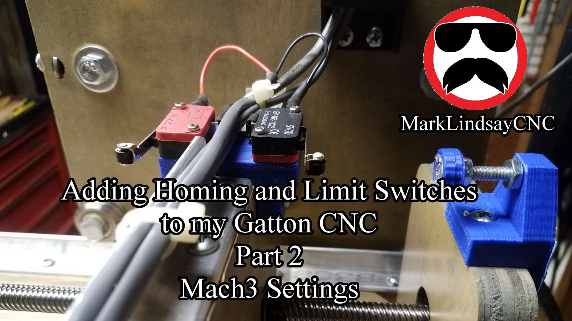
Mounting the limit switches themselves was pretty straight forward. I put the mount and bumper where it was supposed to go, mounted the switches to the mount, and ran the wire through the drag chain I had previously mounted on the axes. At the other end, I connected positive wire to the breakout board, the negative wire to the grounding terminal strip I mounted under my table, and the cable’s shielding wire to that same strip. That’s all there is to it.
The main thing to remember is to connect the shielding wires to ground on one end only. DO NOT connect both ends! If you do, you’ll create a ground loop that will cause you problems almost immediately. So remember – connect one end of the shielding wires to ground, and don’t connect the other end to anything. Trim them back flush with the cable’s outer insulation and leave them be.
With everything hooked up, I then got into Mach3 and configured the switches to work as both homing and limit switches. That was straight forward enough as well. There are just a number of steps to take to make sure you have them configured correctly. The most important step is to remember to set the general configuration so that the slave axis homes with the master axis. I explain this in detail in the video below that accompanies this blog post. The second most important step is to remember to go back into the CONFIG menu in Mach3 and click Save Settings after you finish configuring the homing and limit switches, before you exit Mach3.
While the process wasn’t difficult, it was pretty involved. There’s a lot to do, a bit to remember, and quite a bit to explain. So much, in fact, that I broke it up into 2 separate videos, which I’ve posted below.
So where do I stand right now? As I said earlier, the major construction is finished. I have the spoilboard mounted and it’s looking good (video on the way!) Right now I’m putting together a dust collection system, then I can surface the spoilboard, then fire this puppy up!
Have a question or comment? Leave it in the comments below. If you’d prefer, go over to the Contact Us page and submit it to me there.
Until the next update, take care and have fun!
[amazon_link asins=‘B01H54ULSO,B000A804DA,B000ALY4E2,B000CD1T0A,B0000DCBK0,B00005QEVQ,B000C02BXW,B0002YQ3KA,B0000225XE,B019G0VVTI’ template=’MarksProductCarousel’ store=’malicn-20′ marketplace=’US’ link_id=’562e4ff5-c7f5-11e7-877d-c1fd5f75bd67′]
[/expand]