Gatton CNC Build Part 10 – Router Mount and Tramming Plates
In this installment of my Gatton CNC build, I modified, drilled, and assembled the router mount assembly, then added two plates to the sides of the Z box that will allow me to adjust the router mount when it comes time to tram the router.
So what is tramming? Well, without getting too deeply into it here, tram is the squareness of your router or spindle to the table. Adjusting that squareness, whether it be along the X axis or Y axis, is known as tramming. The two plates I made will help me to more precisely adjust that squareness, then lock it into position while I tighten the mount, securing it to the Z box.
The first modification I made to the router mount was to take it over to the table saw and cut about a blade’s width off of each side of the mount plate. The router mount plate needs to be slightly narrower than the Z box front panel to give the mount room to move when it comes time to adjust it.
In deciding on what type of nut to use in the router clamp, I used 1/4” 20tpi weld nuts. I think square 1/4” 20tpi nuts would work just fine for this as well. I wouldn’t use standard hex nuts, as they could easily break loose and spin inside the hole, where a square nut wouldn’t be able to. Follow along with the video to see further details of the assembly of the router mount.
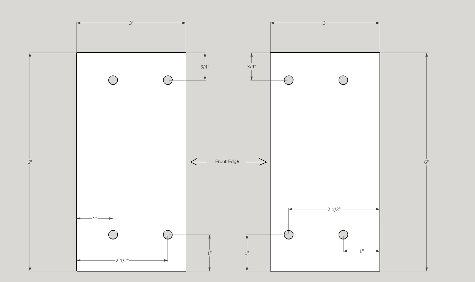
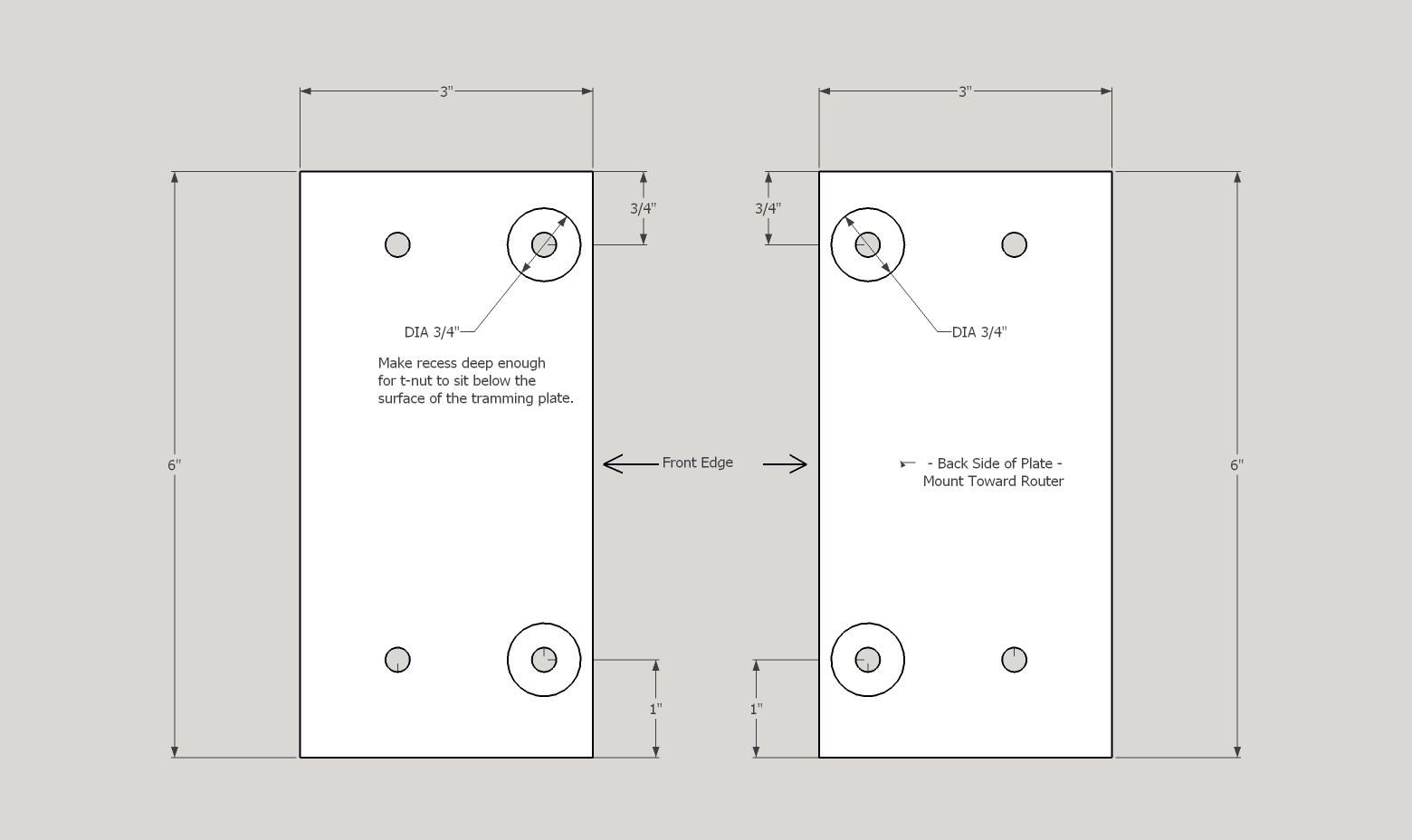
The tramming plates are very simple to make out of 3/4” plywood left over from the construction of the gantry. In fact, I made mine out of the leftover scrap from the gantry bottom panel. Using the measurements in the picture below, I first used a 3/4” forstner bit to drill a recess into the back side of each plate. One thing to keep in mind when making the plates is that you are making one for the left side and another for the right side. These two plates mirror each other, so make sure you drill these recesses on the correct side of each plate.
With the recesses cut deep enough that a #10 – 24 T-nut will sit below the surface of the plywood, I then used the correct size twist drill bit to drill the rest of the required holes. The size of the bit needed will depend on the outside diameter of the shank of the T-nuts you use.
With everything stained and finished, I assembled the router mount, then loosely attached it to the Z box using standard 1/4” – 20tpi hex head nuts (after first trying socket head cap screws and deciding against them.) I then aligned the bottom edge of the tramming plates with the bottom edge of the Z box, and clamped them into place, keeping the back edge of the tramming plates held tight against the edge of the aluminum angle on the Z box.
Once clamped into place, I drilled pilot holes, and secured the plates with #10 – 1 1/4” long exterior grade woodscrews. I used my impact driver to drive the screws most of the way in, then finished tightening the screws by hand to prevent the screws from going all the way through the sides of the Z box.
I then let the glue on the router mount cure overnight before mounting my Porter Cable 890 router motor.
That’s all there is to it!
As usual, thanks for stopping by, and remember that if you have any questions or comments for me, feel free to leave them here, or you can email me through the Contact Us link.
Good luck with your build!
Have a question or comment? Leave it in the comments below. If you’d prefer, go over to the Contact Us page and submit it to me there.
Until the next update, take care and have fun!


One Comment
Melvin
Great idea! Thanks!